EGR Delete kit installation.
EGR Delete reinstallation procedure for the 3.0 TDI Gen 2 V6 diesel turbo. Sequential — follow IM-002 before this manual. This manual only focuses on the EGR delete portion
How to use this document
Read it through, twice, before you pick up a wrench.
This manual walks you through installing the EGR delete kit, starting from the point where the intake is off, the cooler is out and all plastic flanges are removed. Follow IM-002 to reach this stage.
Every gasket is single-use.
Every gasket, seal, O-ring and air-guide pipe seal in this procedure is single-use. Have the replacements on hand before you start — reusing them is the most common cause of a coolant or boost leak after this job.
Document contents
What's in this manual.
4 numbered sections, 23 pages, 0 torque tables and 1 replace-only checklist. Page references on the right.
Initial Stage
This step begins with a blank oil cooler plate. Everything will get built up from here
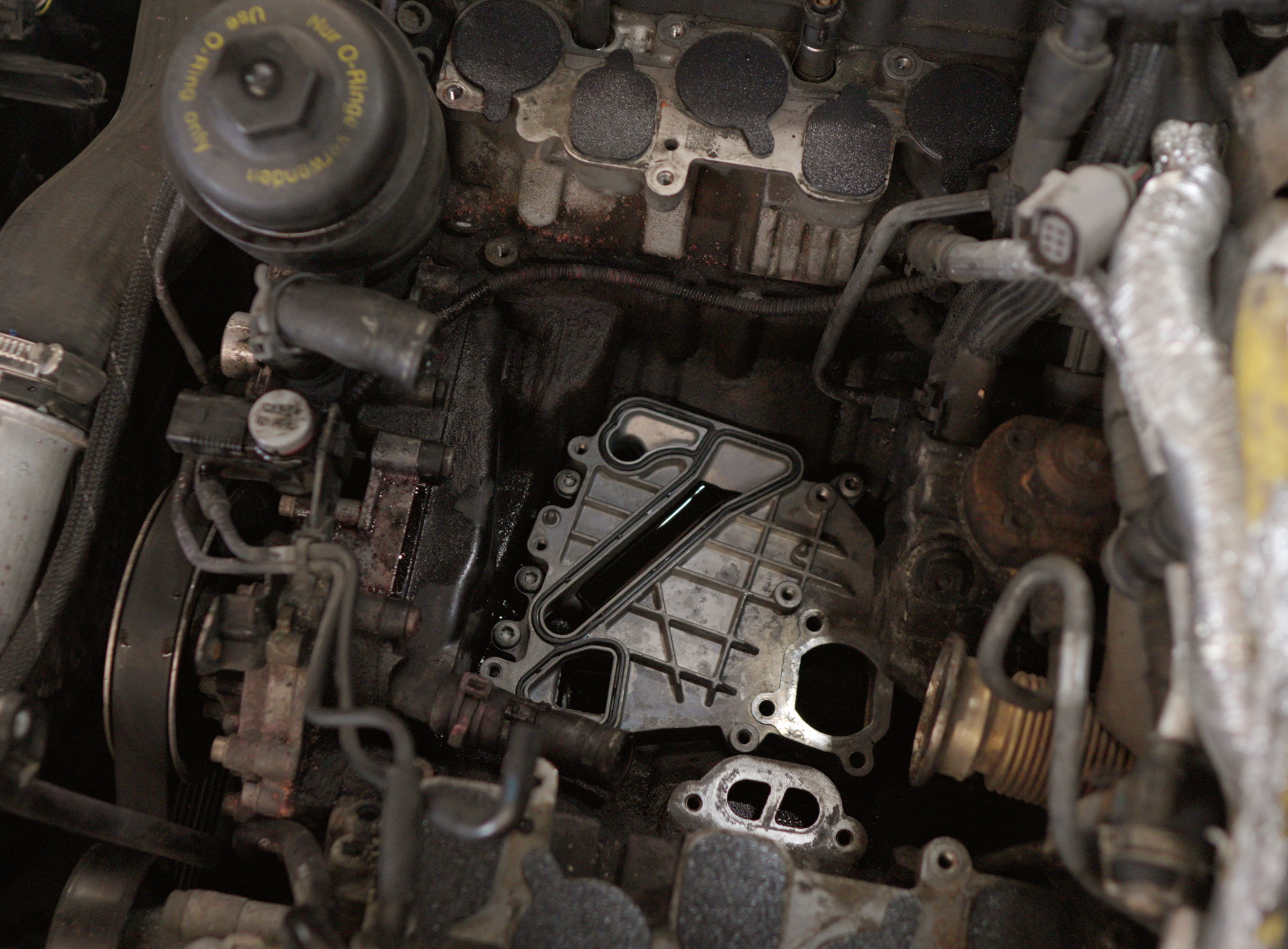
⚠ Caution · contamination
Protect the seals during installation. Must remain perfectly clean and undamaged. Or else, you will hate yourself...
Preliminary work
- Clean, Clean, Clean all sealing surfacesBrake Clean
- Apply a small coating of seal lubricant to the sealsMOLYKOTE® 55
Installation sequence · steps 01–09
Installing the billet bypass valve
Ensure all mating surfaces are clean. Use brake cleaner and shop towels right before installing the valve
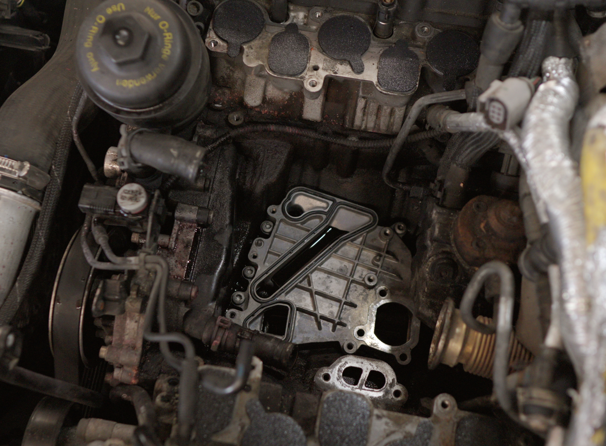
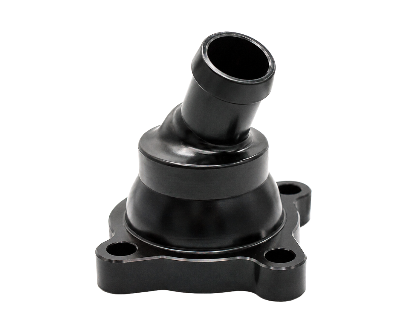
Drop in the coolant bypass valve A00007 onto the oil cooler plate and torque the 3x T30 fasteners to 9 Nm
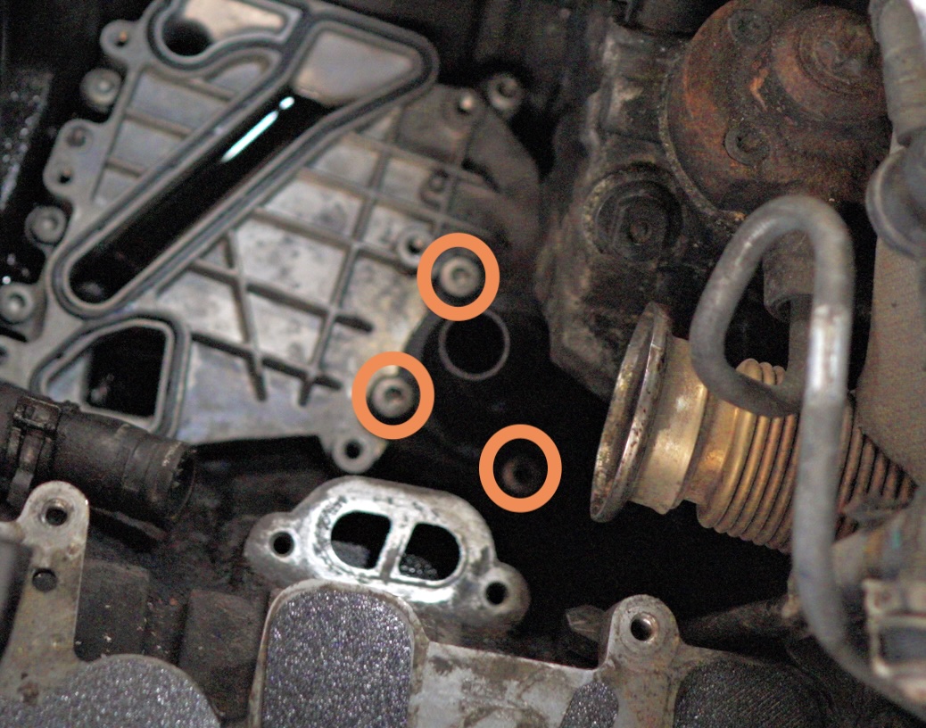
A. Press on hose P10048 hose onto the side port of the intermediate flange A00005
B. Slide on 2x hose clamps 5076K44 loosely over the hose P10048 as shown on the image below
C. Bring that assembly into the engine valley and push on the other end of the hose P10048 onto the top barb of the coolant bypass valve A00007 installed in the previous step
Do not fasten intermediate flange A00005 yet, leave it loose!
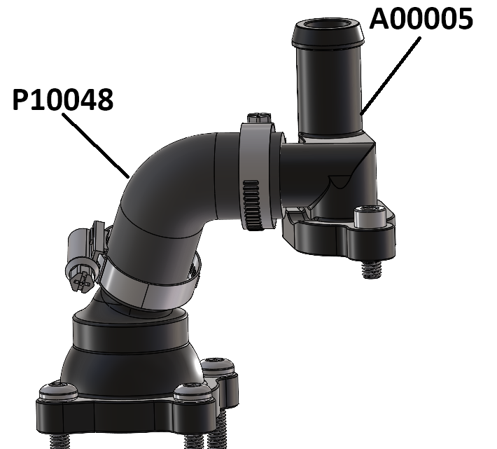
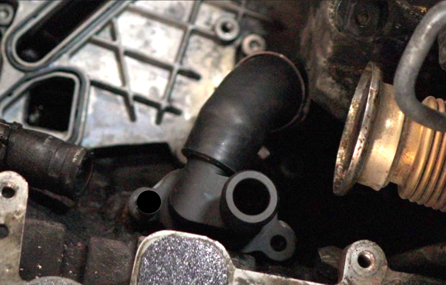
Torque the circled hose clamp 5076K44 to 3.3 Nm.
Ensure it is oriented per the image below
Do not torque the other hose clamp yet
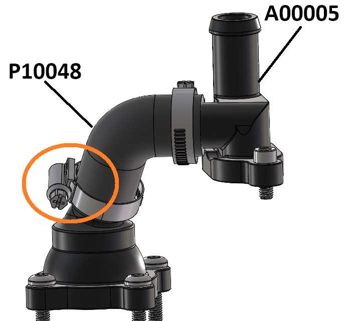
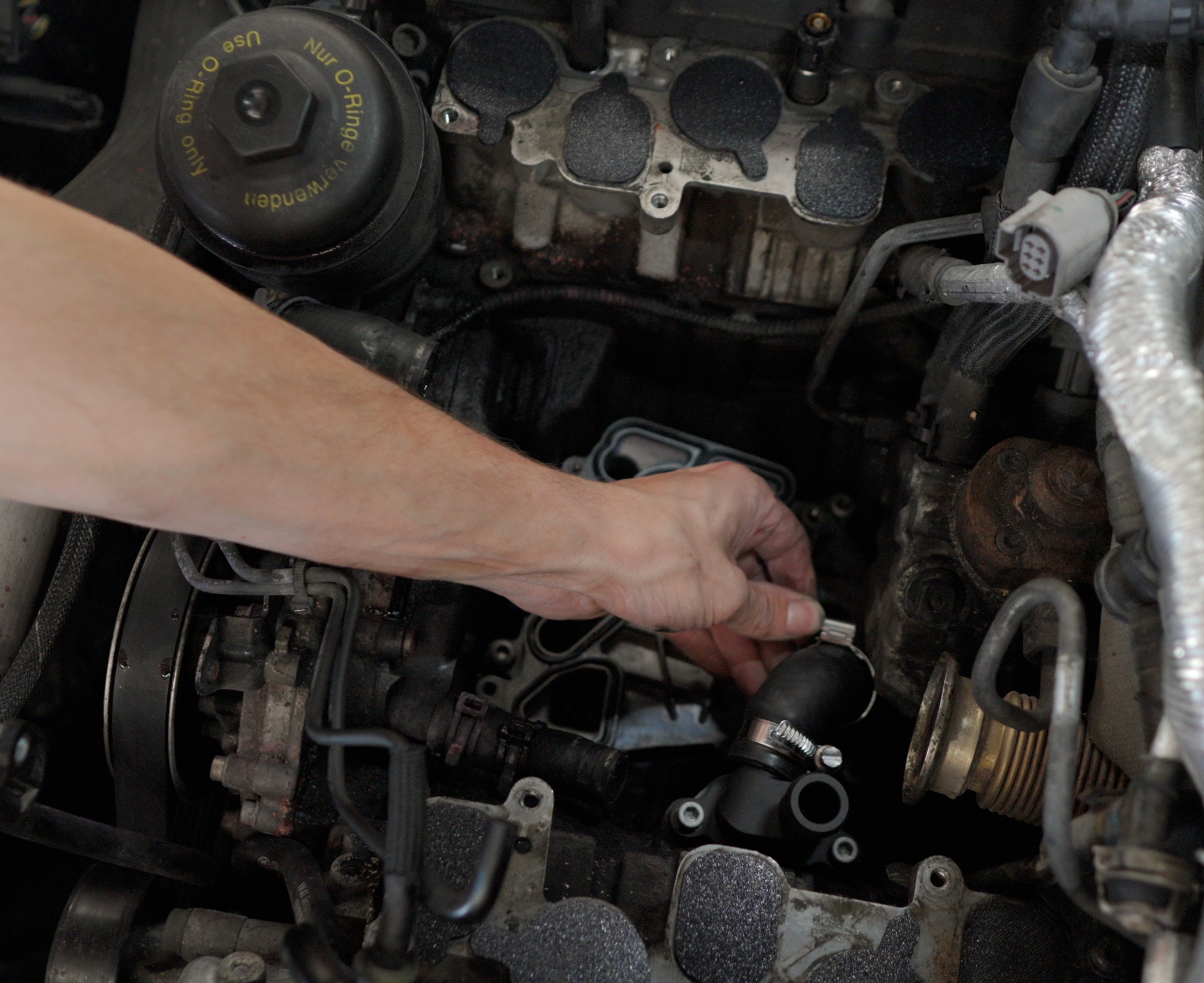
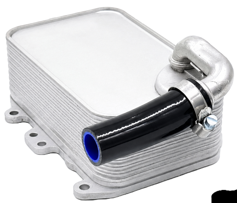
With the new hose P10049 already fitted over the oil cooler barb, drop in the oil cooler into the engine valley and fit the other end of the hose onto the barb of the front engine cover
Ensure oil cooler bottom face is clean! and there are 2x loose hose clamps on the oil cooler hose
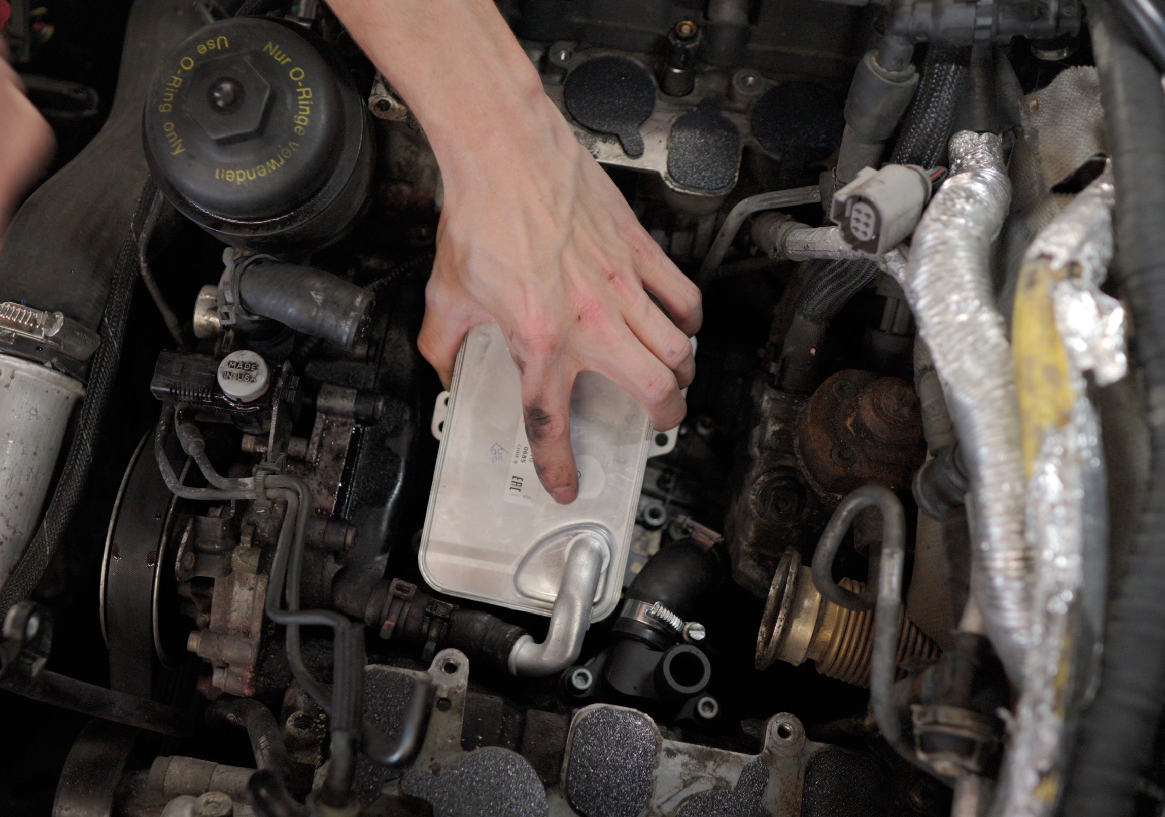
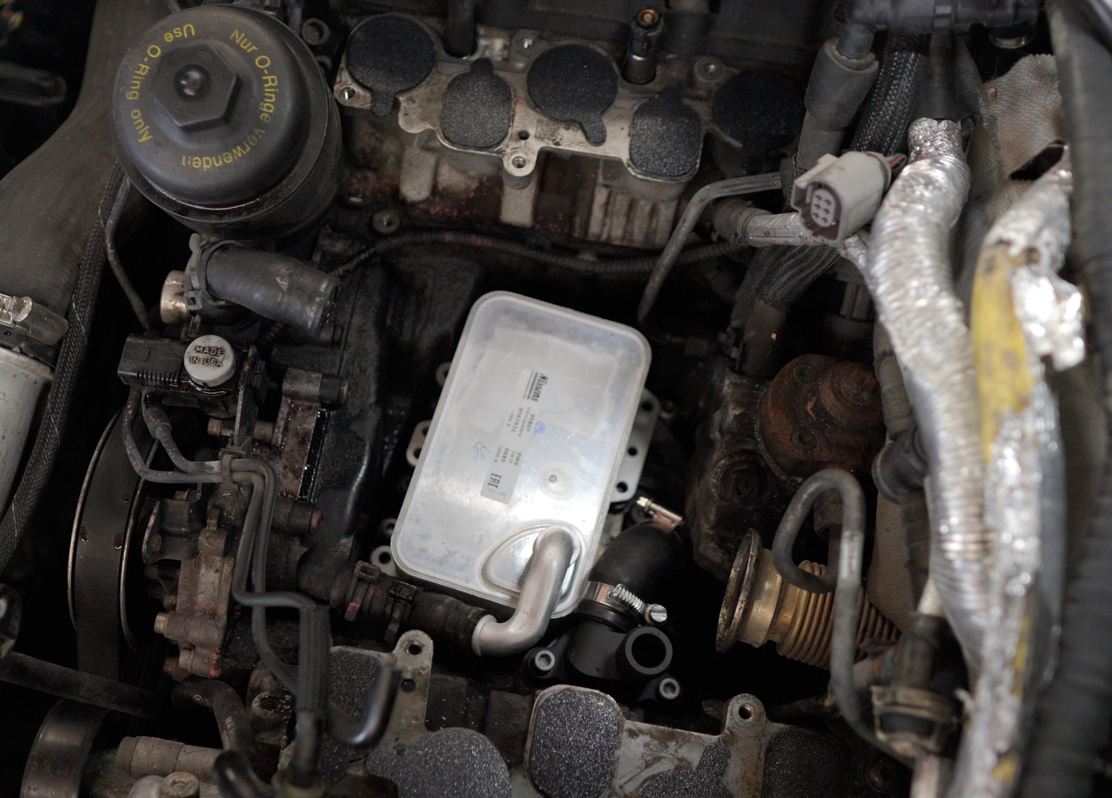
Torque the oil cooler bolts to 9 Nm
We left the intermediate flange unfastened in step 03 because we need to push it towards the rear of the engine arrow to get a T30 bit on an extension in there, to torque the oil cooler
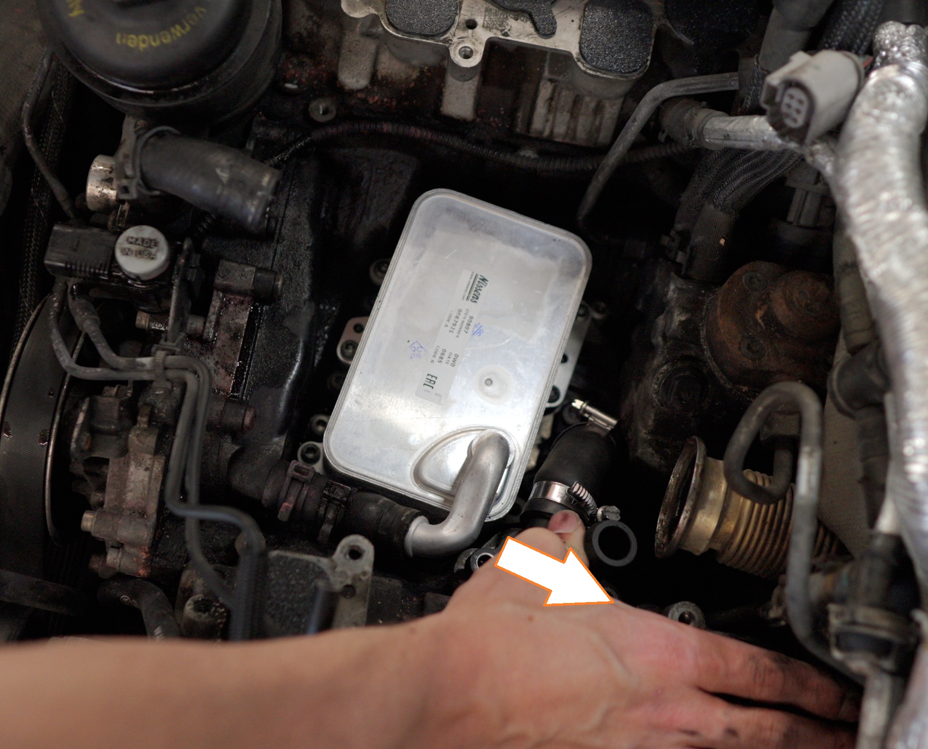

Install 2x fasteners 95263A531 to secure the intermediate flange A00005 and torque to 9 Nm
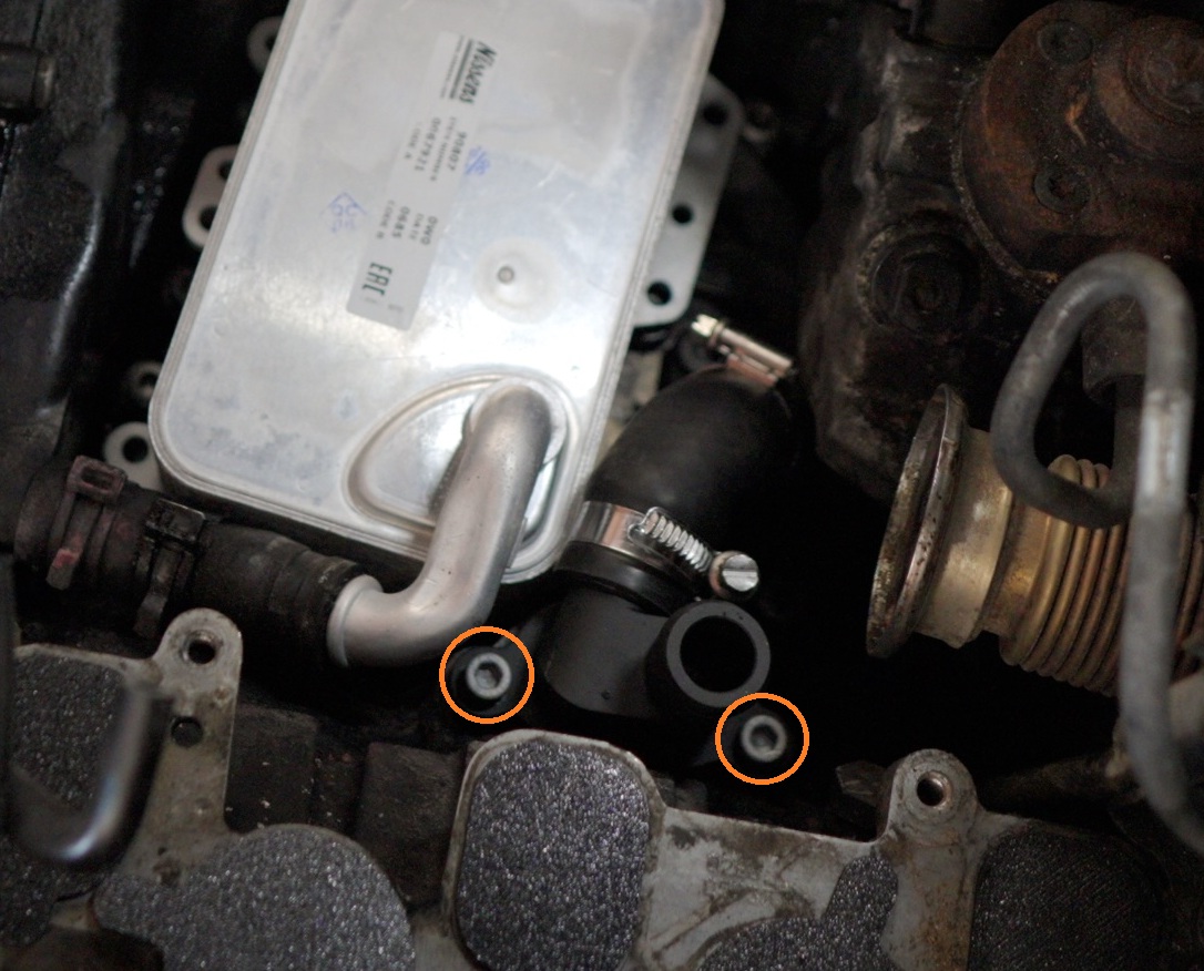
Torque the circled hose clamp 5076K44 to 3.3 Nm.
Ensure it is oriented per the image below
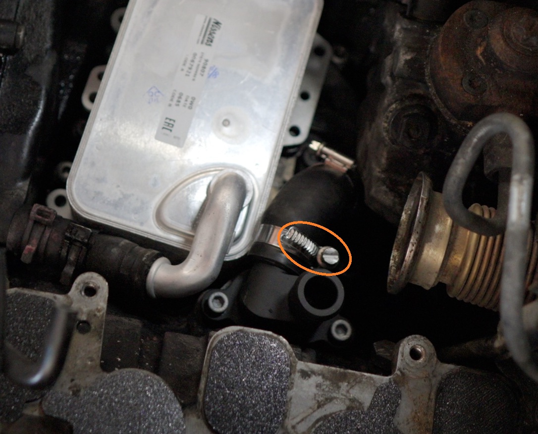
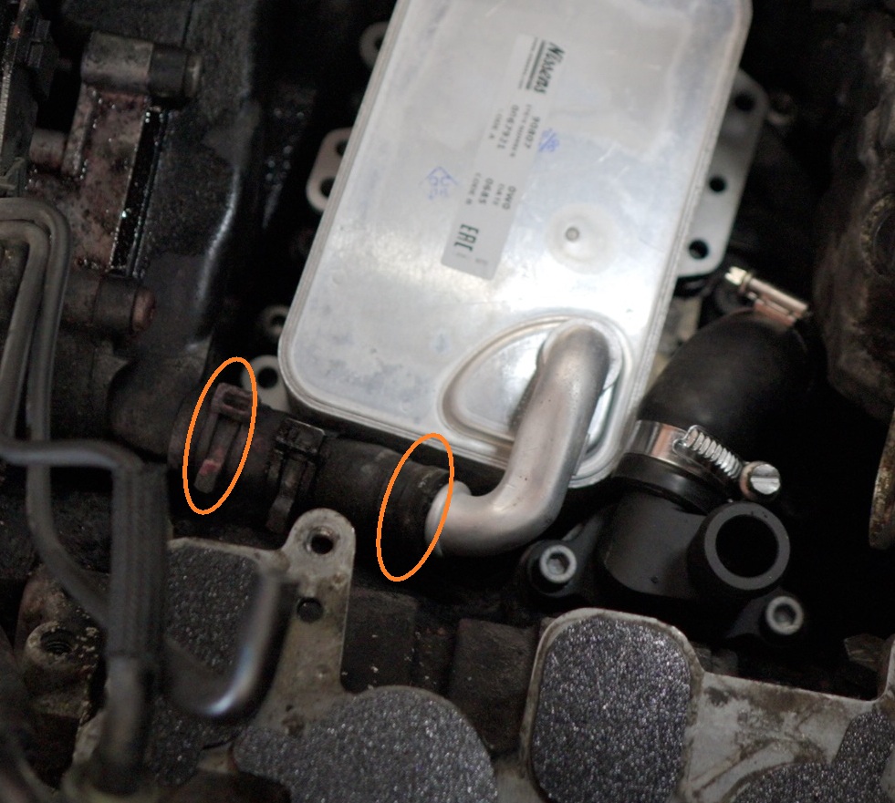
Torque the two circled hose clamp 5076K44 to 3.3 Nm.
Ensure it is oriented per the image below
Removal sequence · steps 01–05
The Actual EGR Cooler Delete
Loosely Preassemble your hoses P10028, P10029, temperature sensor housing A00010 and hose clamps 5076K44 as shown below
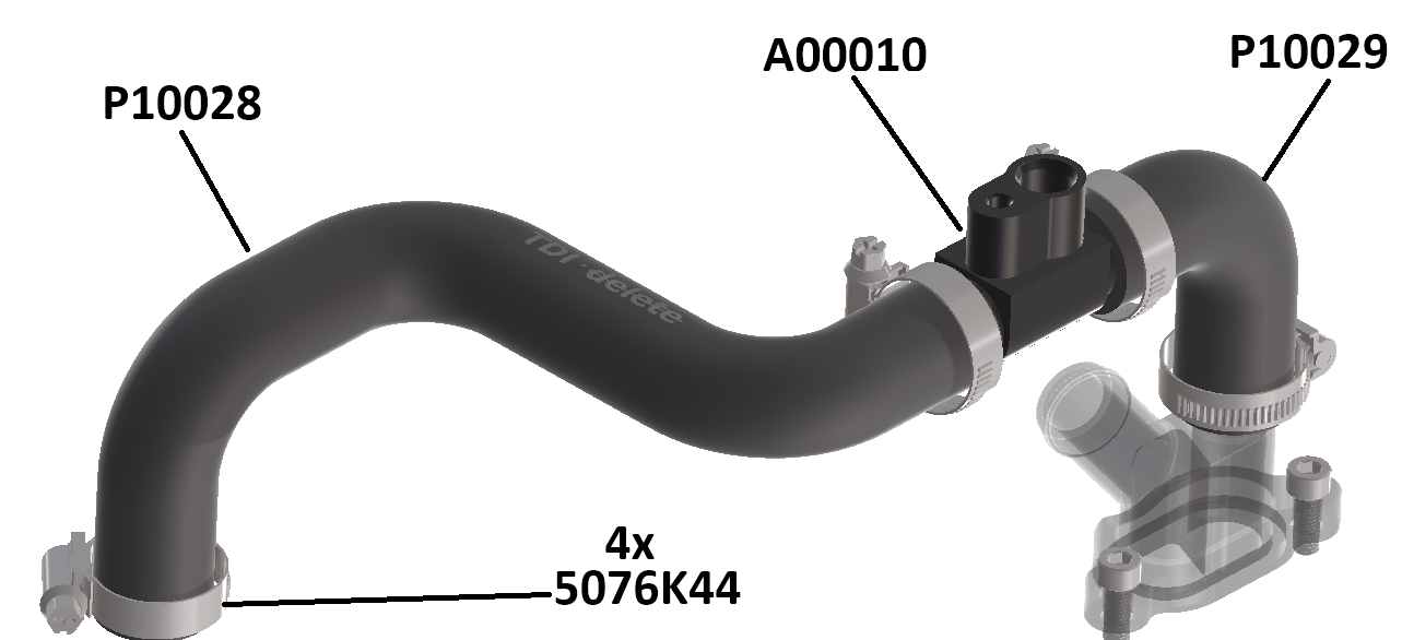
Drop in that assembly into the valley.
-P10028 (Long S shaped hose) Hose end plugs into the oil filter housing barb
-P10029 (Short Elbow) plugs into the top of the intermediate flange A00005
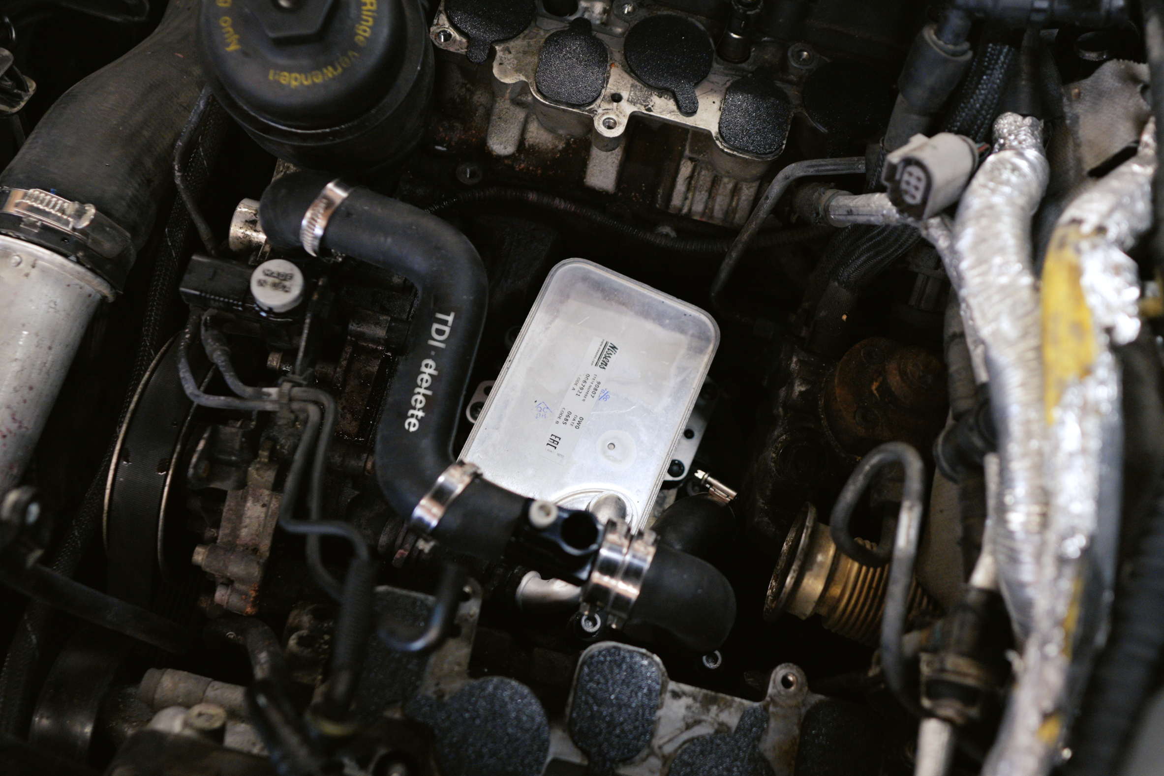
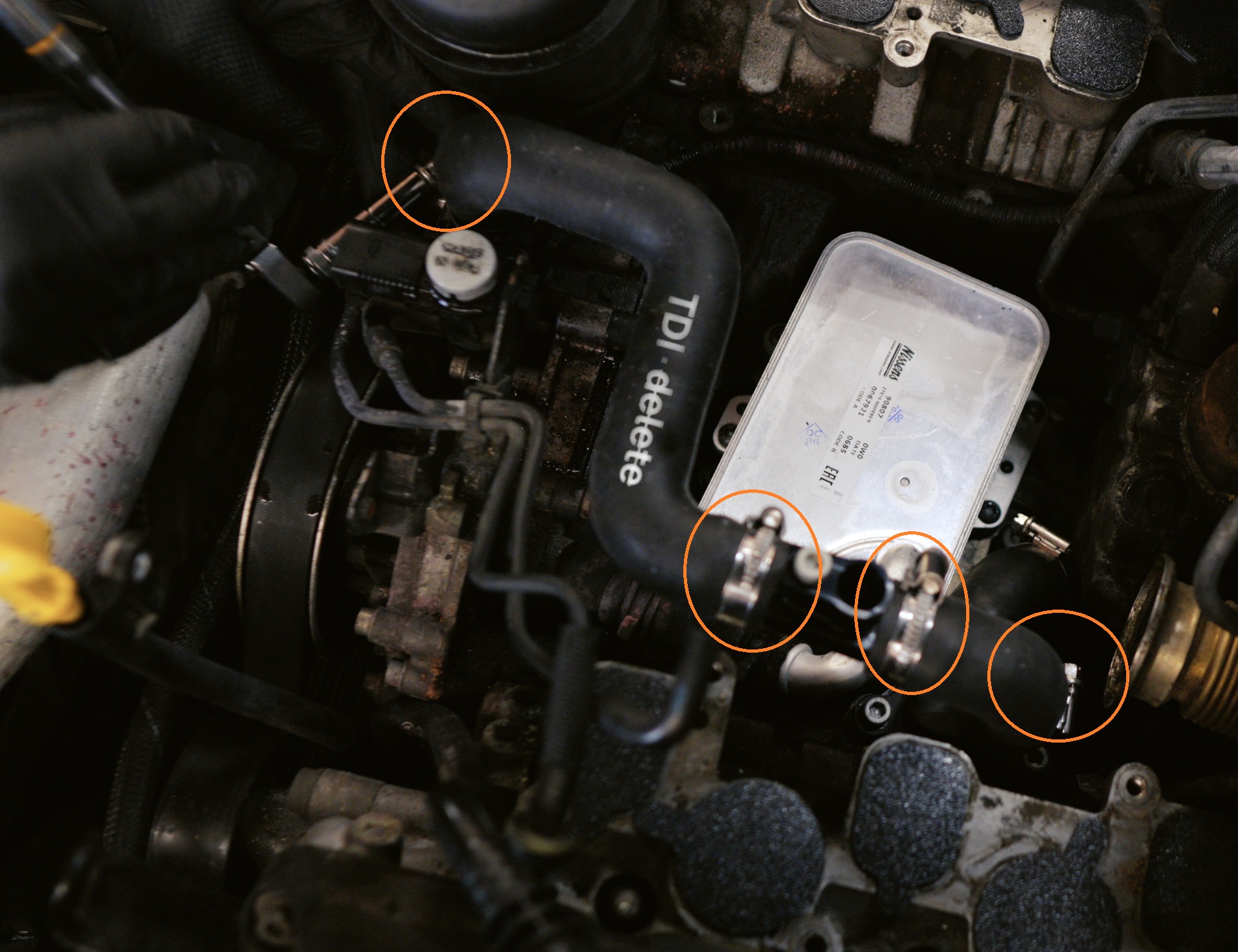
Torque circled hose clamp 5076K44 to 3.3 Nm.
Ensure they are oriented per the image below
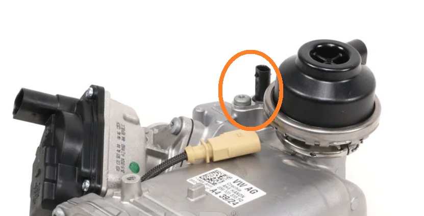
Install coolant temperature sensor into the sensor housing
Note: This sensor is to be removed from the old EGR Cooler and reused
Torque the fastener to 9 Nm
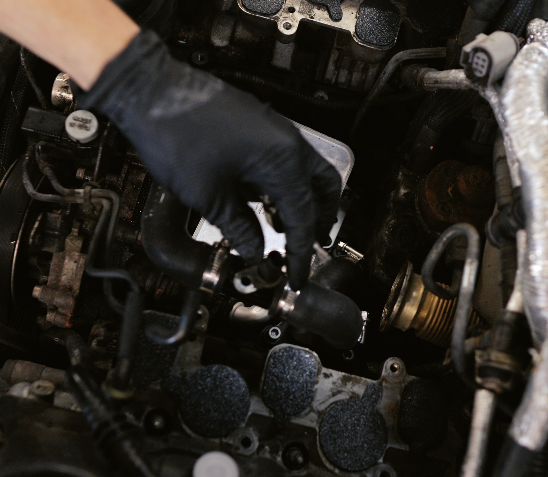
Remove the 2x unused vacuum lines going to the old EGR cooler and old Coolant Bypass Valve and install Cap P10030 on the barbs where these vacuum lines used to live
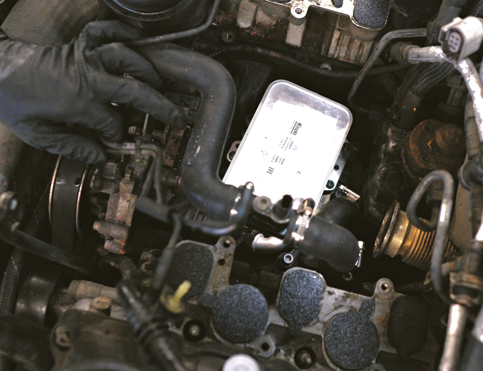
Removal sequence · steps 06–12
EGR Block-Off Plates
Remove the metal EGR exhaust hose from the turbo. These are held in by 2x T30 screws
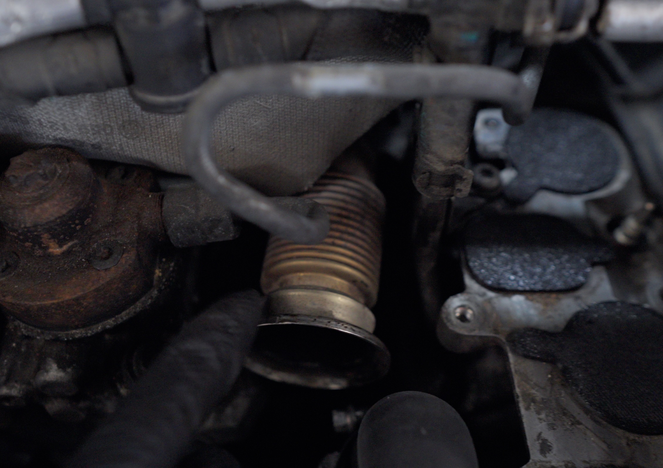
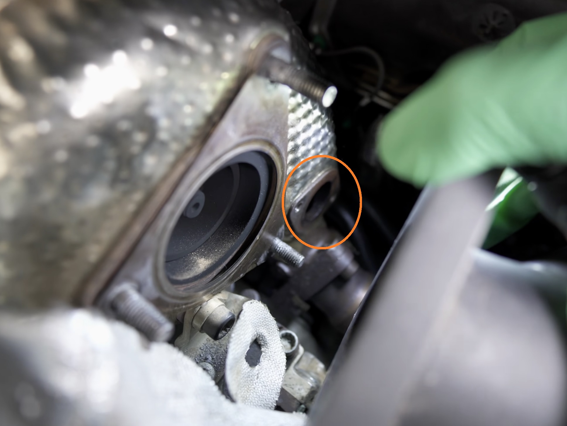
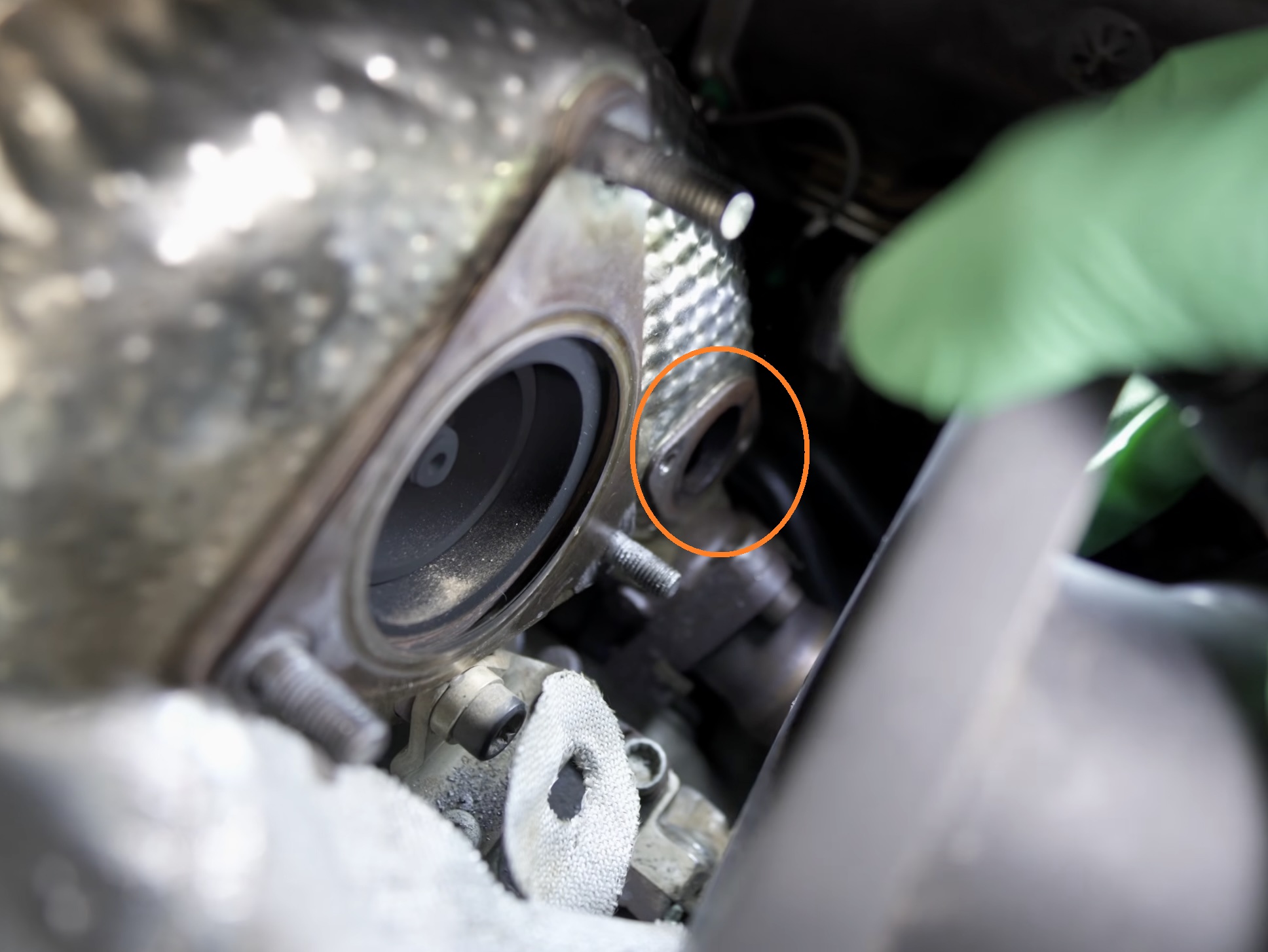
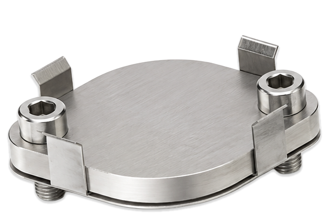
Install the turbo blockoff plate (Stainless) from the kit A10005 and torque to 9 Nm
Ensure the metal gasket is installed
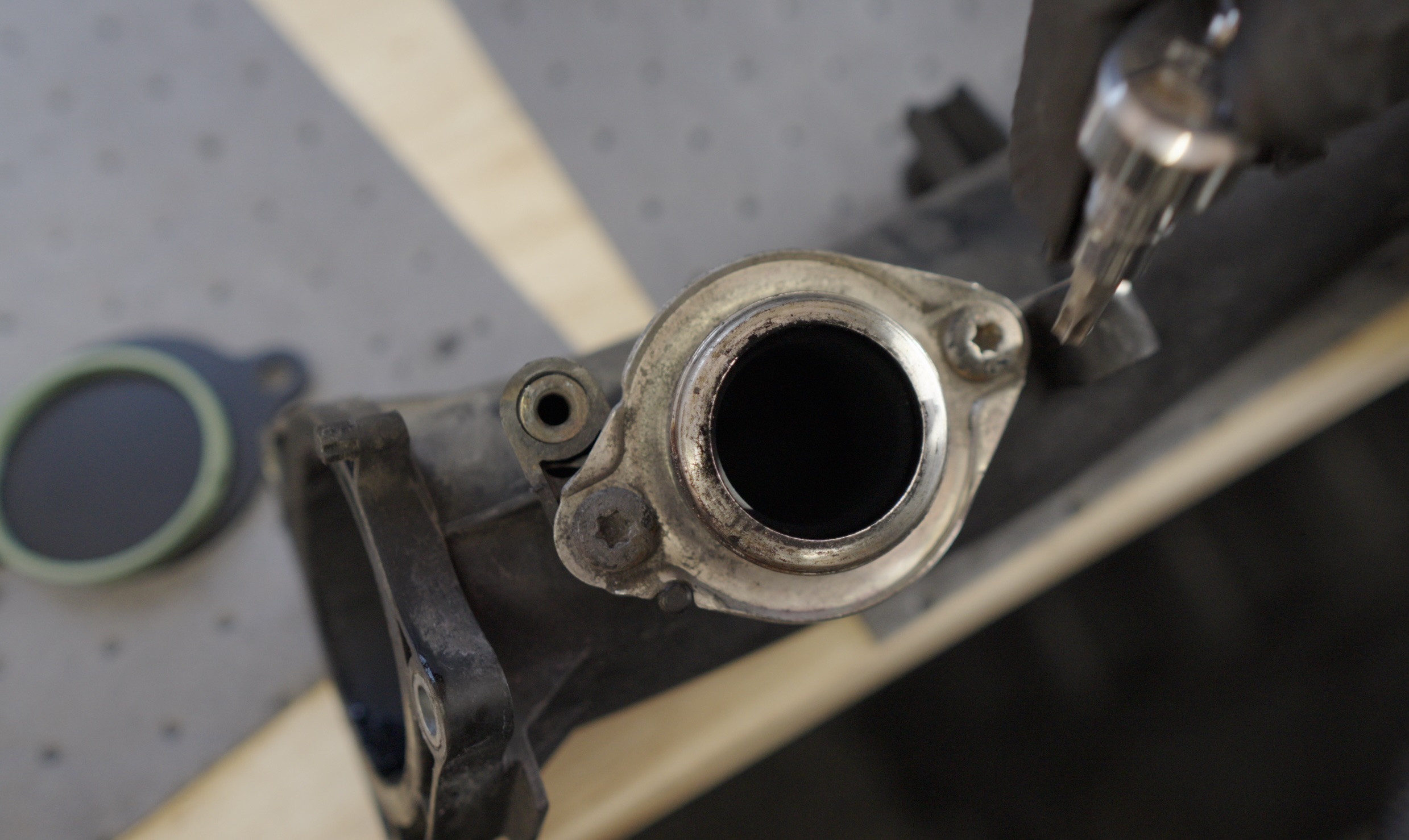
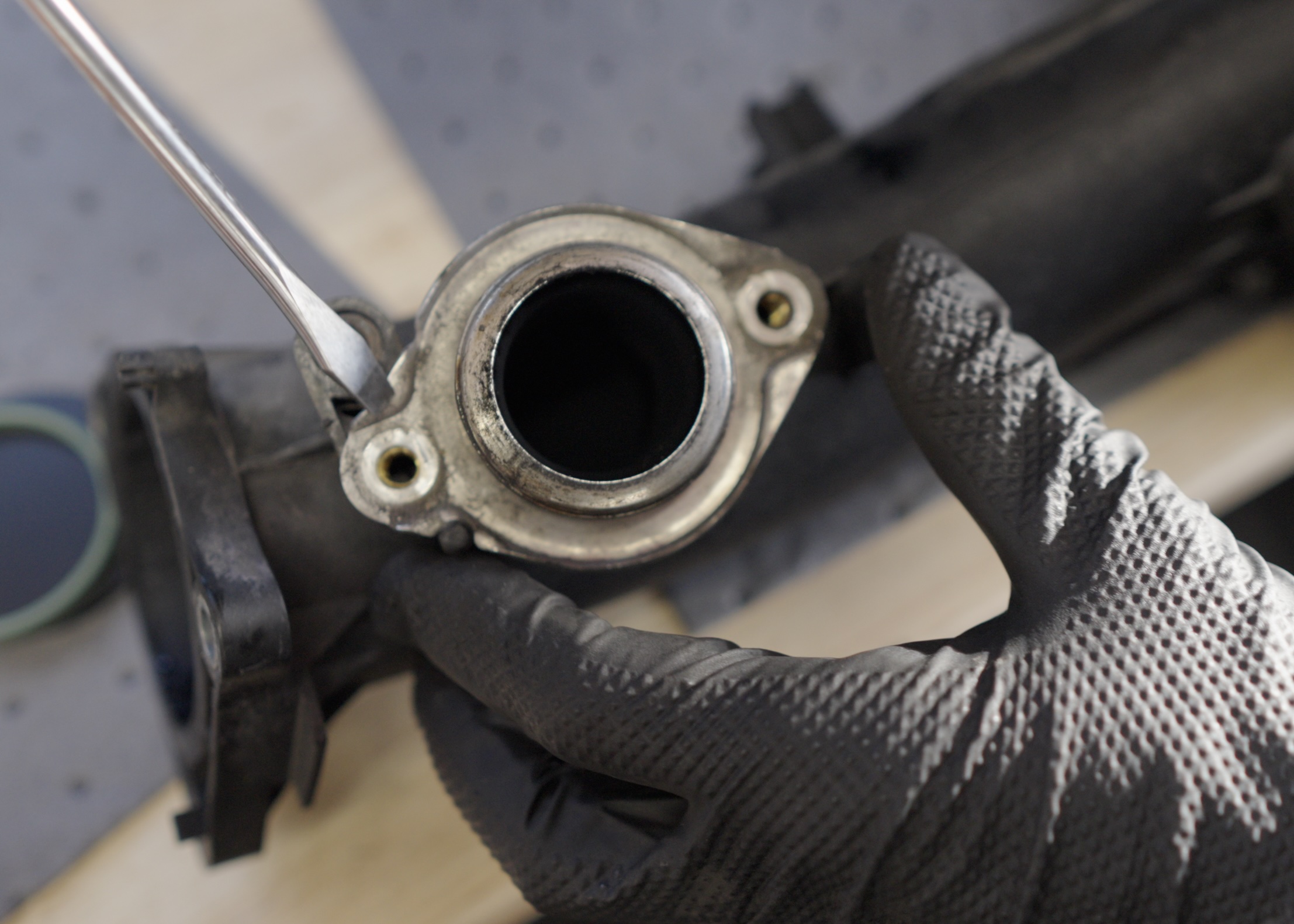
Remove the 2x T30 screws holding in the intake EGR flange and remove it.
You can pry using a screw driver on the pry tab
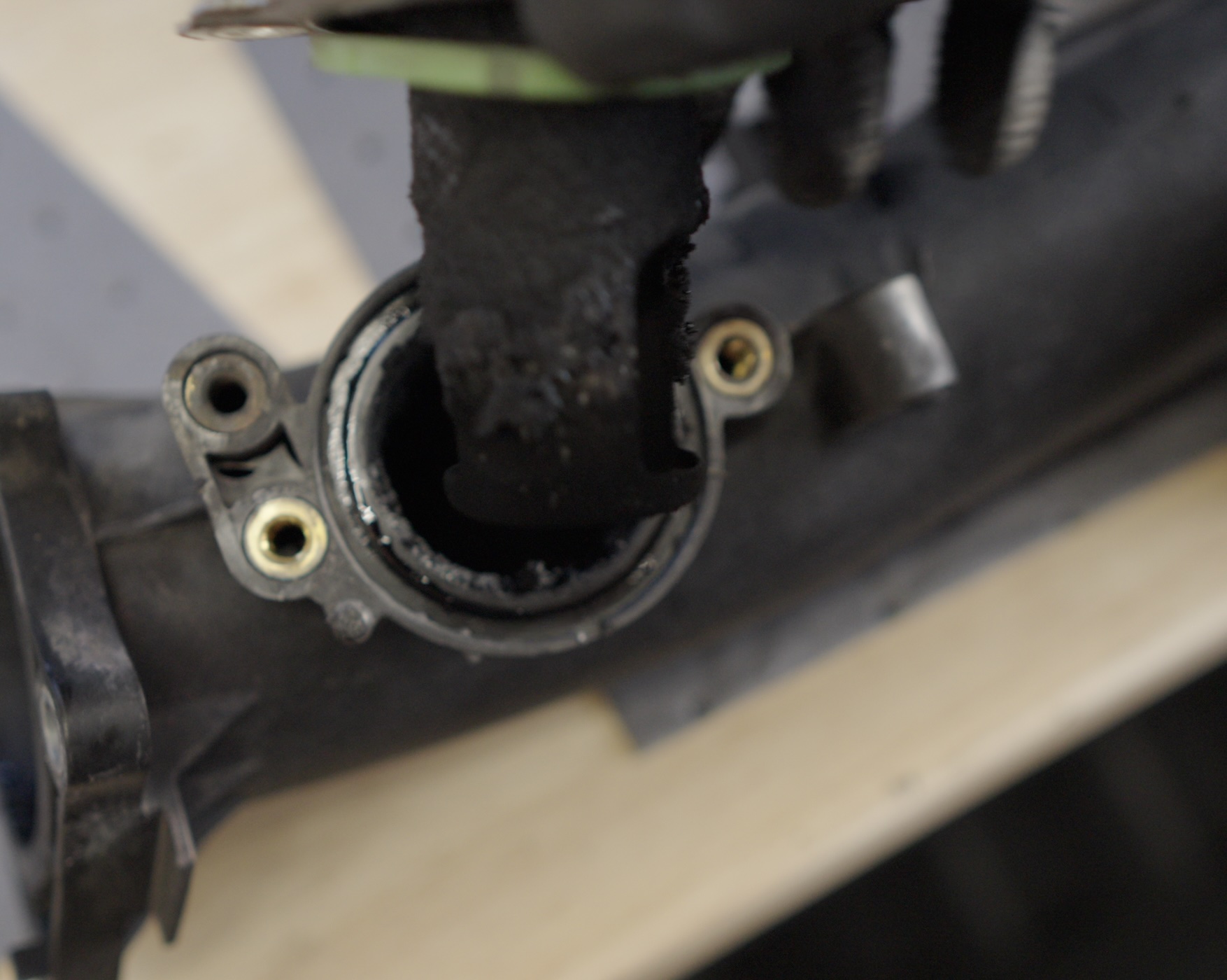
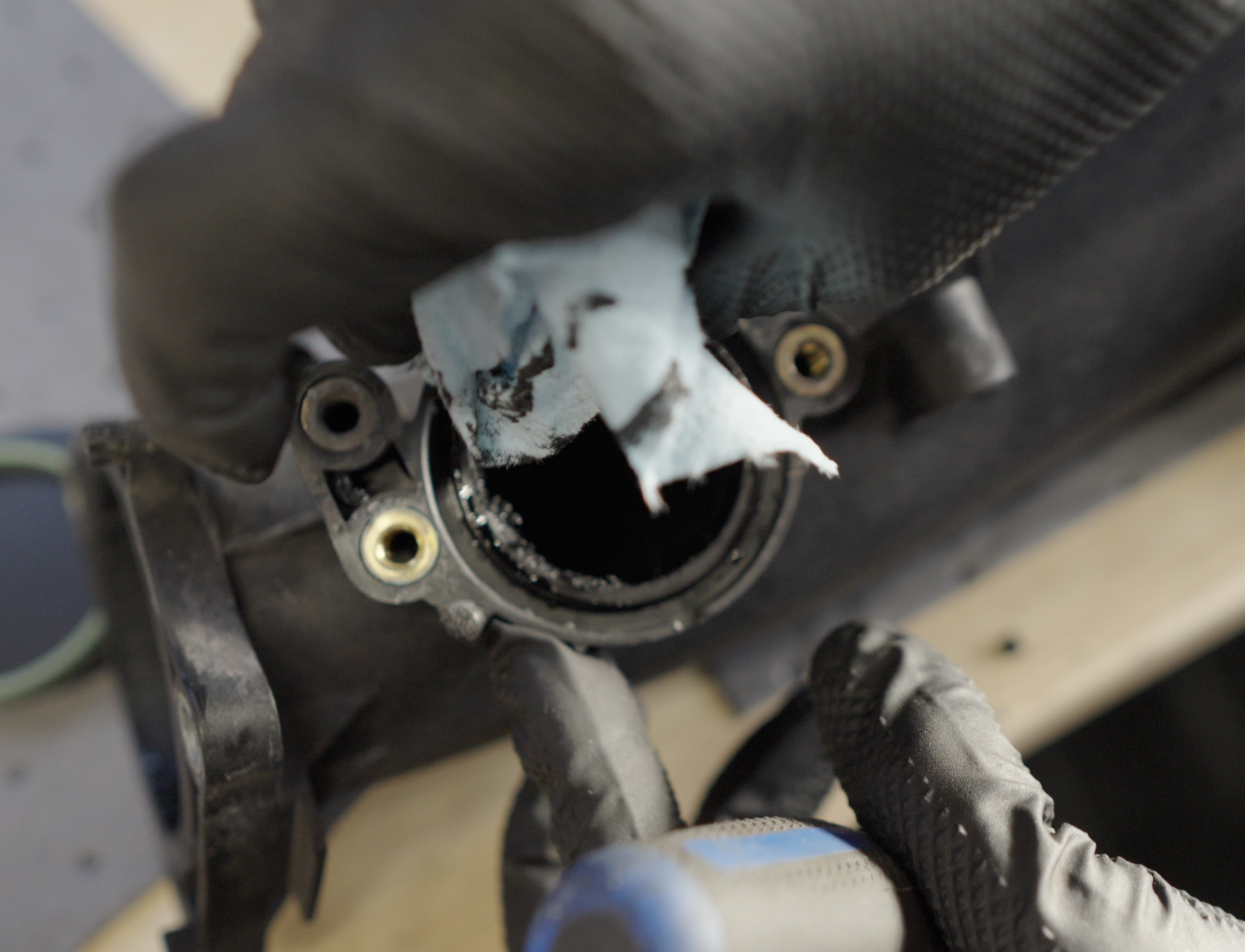
Clean Clean Clean the seal groove and port. Use Brake Cleaner and Shop Towels
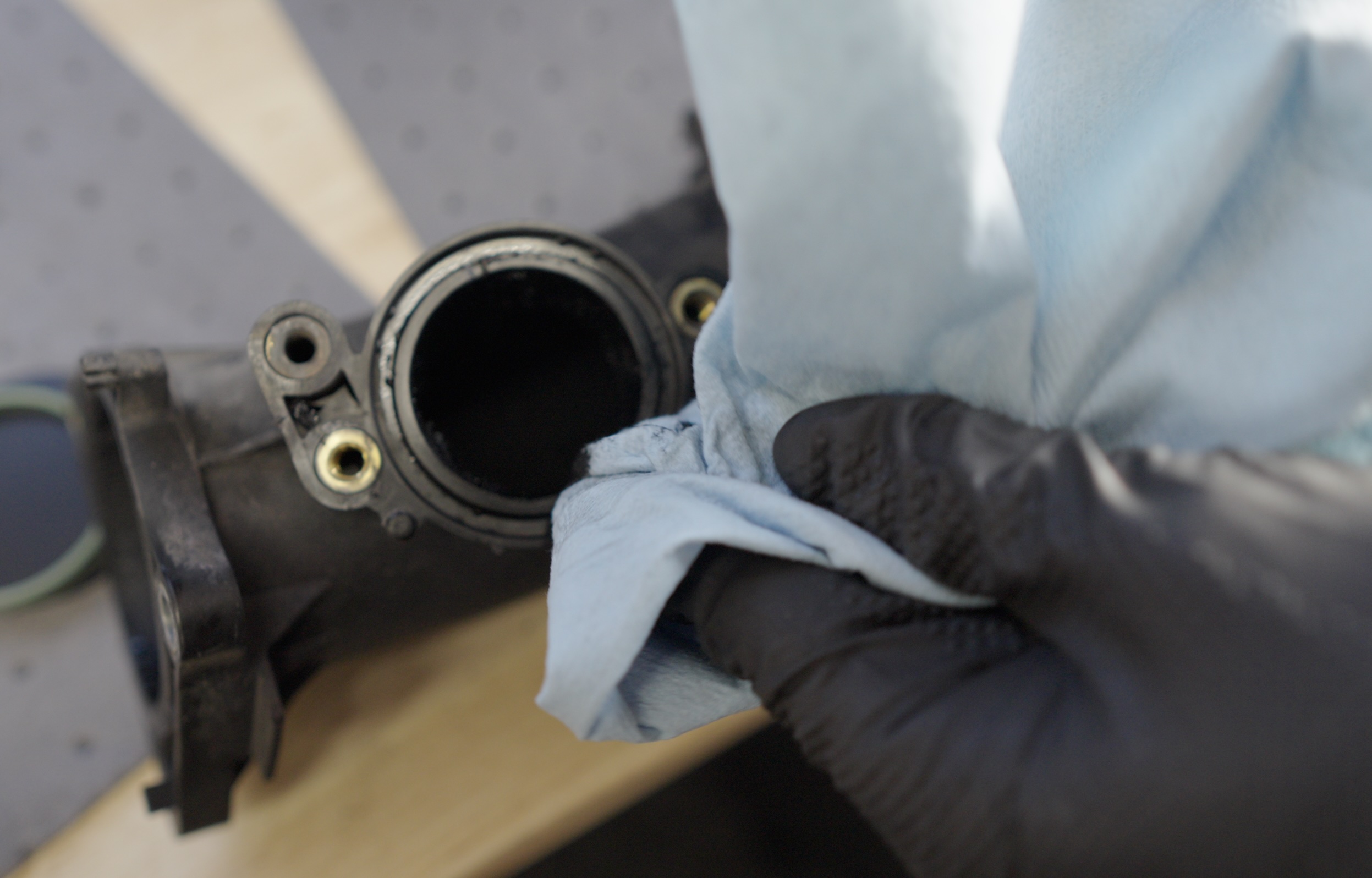
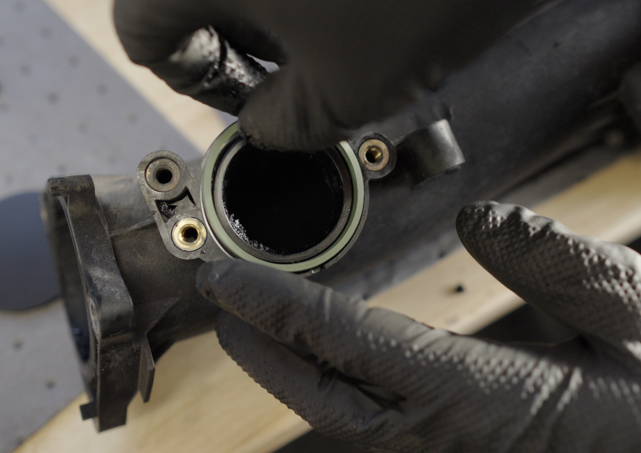
Install a new EGR Intake Seal 059131815 from the kit A10005
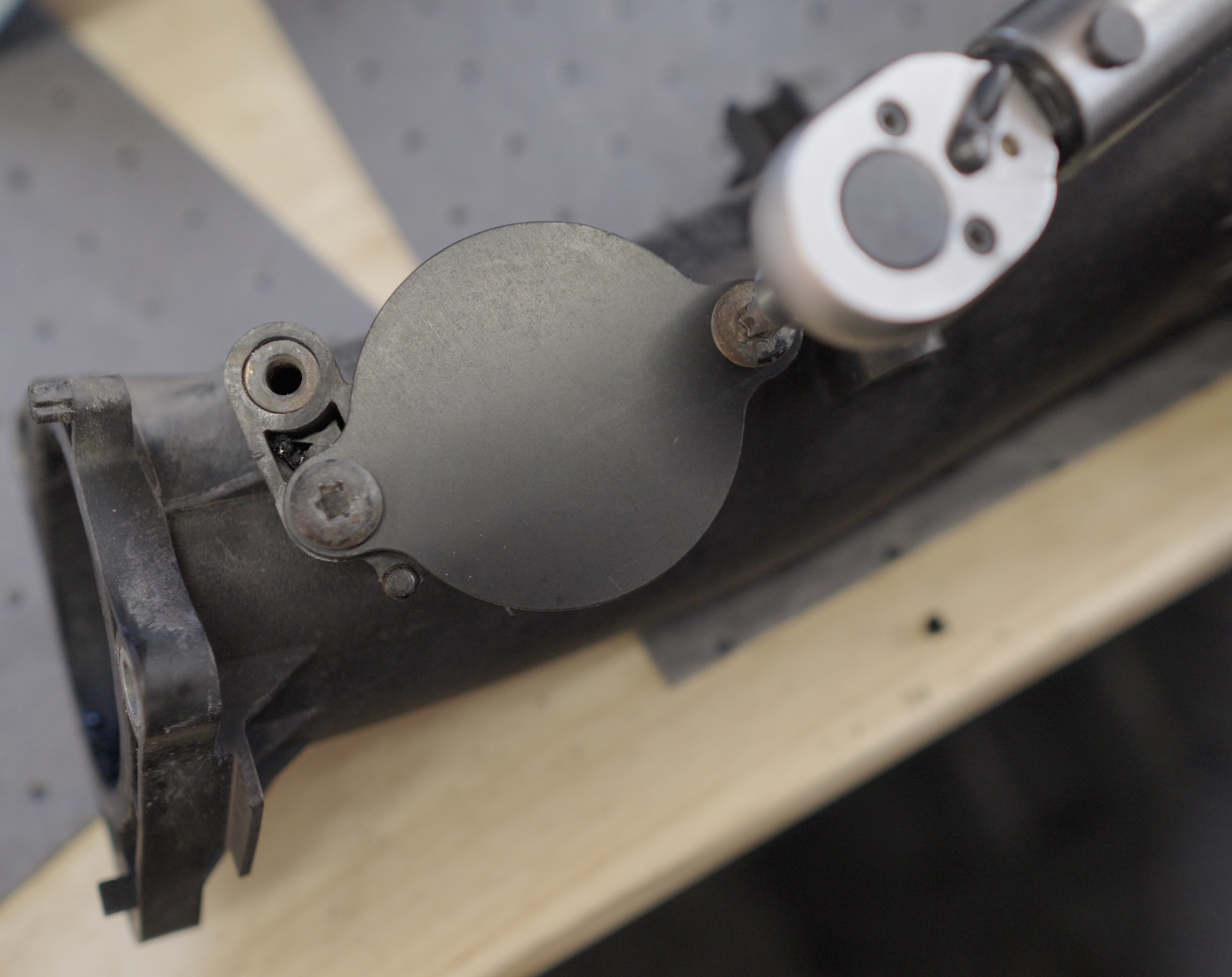
Install the block-off plate (Black One) from the kit A10005
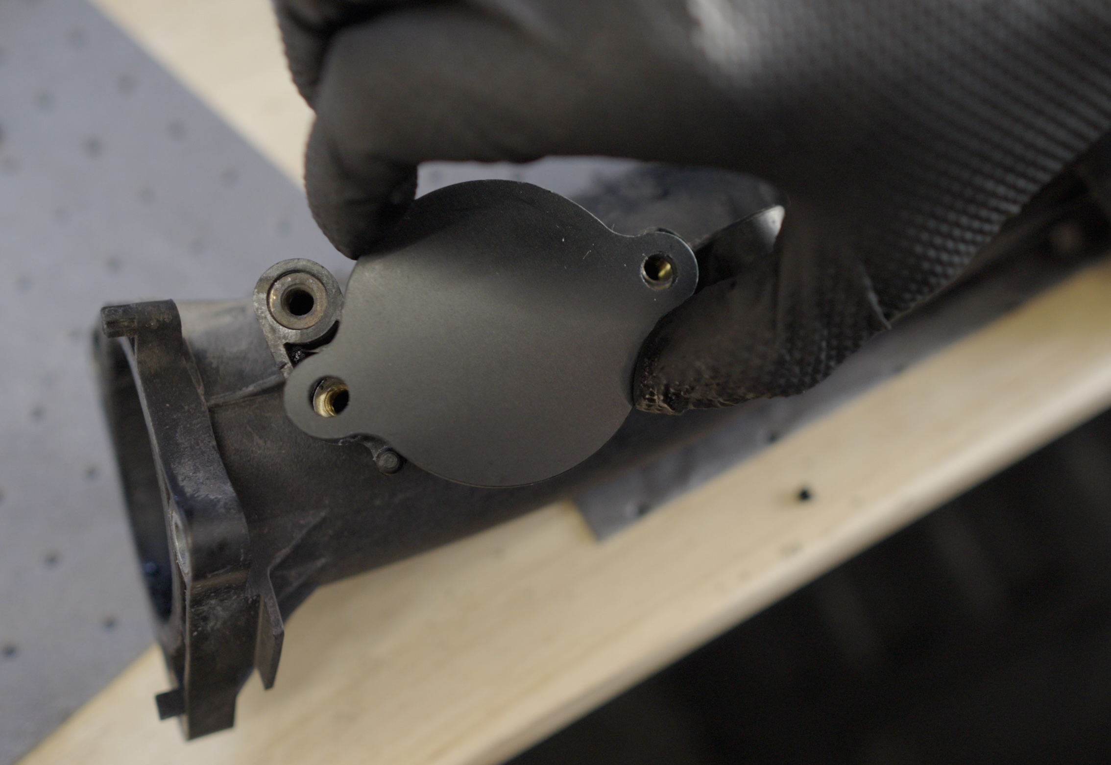
Torque the fasteners to 9 Nm
Section 4.3 · sheet 1 of 2
Intake manifold — the 3-step torque.
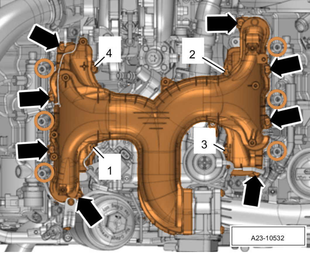
Fit new seals, set the manifold, then follow the published 3-step torque sequence below. Do not freelance — the sequence is what keeps the flange flat.
⬢ The published 3-step sequence
Step 1. Run all screws in as far as they go by hand. Step 2. Torque to 9 Nm in the numbered sequence shown on the drawing. Step 3. Go around again at 9 Nm in any order.
 A23-10532
- Fit new intake manifold seals on the cylinder head, a new flap-motor seal, and new air-guide-pipe seals.
- Set the intake manifold in place and start all four manifold screws plus the arrowed screws.
- Tighten the manifold in three steps as published (see callout above).9 Nm × 3
- Reconnect the glow plug electric plug connections.
- Refit the coolant hose and tighten its hose clamp.
- Reconnect the throttle valve control unit plug and refit the air guide hose — air guide pipe to throttle valve screw.9 Nm
- Refit the left air guide pipe holder screws.9 Nm
- Tighten the EGR pipe screw-type clamp.
Section 4.3 · sheet 2 of 2
Intake manifold — harness, lines, cover.
- Refit the oil dipstick guide tube and its securing screw. Push the stoppers back in.
- Refit the flap-motor fastening screw.9 Nm
- Reconnect the two wire-harness plugs.
- Reconnect the coolant temperature sensor plug.
- Reposition the cylinder-head coolant valve holder, tighten its screws, reconnect its plug.
- Fit the high-pressure line holding clamp screw.
- Refit the electric plug connections and check valve into their holder.
- Refit the top high-pressure fuel line and tighten the union nuts. Refit the holding clamp (two screws).
- Refit the line routing and its two screws — line guide screw.4 Nm
- Reconnect the rear coolant hose and press the harness hoses back onto the line routing.
- Refit the engine-cover mounting pins: on the intake manifold (5 Nm), on the air guide pipe (5 Nm). Plug-connection holder screw (4 Nm).5 / 4 Nm
⚠ Note · pre-fit checks
Before you start the engine, double-check: every electric plug clicked home, every hose clamp seated and tight, no rags left in the intake ports, no tools on the engine, the dipstick guide tube is fully home, and the coolant cap is on the reservoir.
- Bleed the fuel system.
- Fill and bleed the cooling system (includes bleeding).
- Fill in engine oil and check the oil level.
- Install the engine cover (design cover).
- If the battery was disconnected, run the post-disconnect work instructions and battery trickle-charge as required.
- Start the engine, bring it to temperature, and check for coolant, oil, fuel and boost leaks at every joint you opened.
Section 06 · replace-only parts checklist
Short list of single-use items across all three procedures. Tick each before you button up.
- Intake manifold seals on cylinder headIntake
- Flap-motor seal on intake manifoldIntake
- Air guide pipe seals (flap motor and throttle body)Intake
- EGR pipe to connection piece clamps (two)EGR
- EGR pipe seal on air guide pipeEGR
- EGR cooler seals, gaskets and O-ringsEGR
- Oil cooler seals (figure items 1, 4, 9)Oil cooler
- Coolant shut-off valve sealOil cooler
Appendix · workshop notes
Your own observations.
Mileage, date, torque-wrench serial, parts numbers, things you'd do differently next time. Write it down — future-you will thank present-you.
End of document
Built once.
Built right.
If you found an error, a clearer way to phrase a step, or a torque value that doesn't match your wrench — let us know. We rev these manuals when the workshop tells us to.