Intake, EGR Cooler & Oil Cooler.
Removal and reinstallation procedure for the 3.0 TDI Gen 2 V6 diesel turbo. Sequential — the intake comes off before the EGR cooler can be reached, and the coolant flanges sit behind it.
How to use this document
Read it through, twice, before you pick up a wrench.
This manual walks you through pulling the intake manifold, removing the complete EGR cooler assembly, freeing the coolant flanges that sit behind it, and putting it all back together with the correct torque on every fastener. The work is sequential — the reassembly section is not “reverse order with no detail”. It calls out the torque on each fastener and flags every seal that must be replaced.
Every gasket is single-use.
Every gasket, seal, O-ring and air-guide pipe seal in this procedure is single-use. Have the replacements on hand before you start — reusing them is the most common cause of a coolant or boost leak after this job.
The 3-step intake sequence matters.
The intake manifold uses a published 3-step torque sequence (hand-tight → 9 Nm in order → 9 Nm any order). Skipping the sequence will warp the flange and cause a leak. Keep the torque page open while you reassemble.
Document contents
What's in this manual.
5 numbered sections, 42 pages, 3 torque tables and 1 replace-only checklist. Page references on the right.
Torque reference · sheet 1 of 3
Intake manifold.
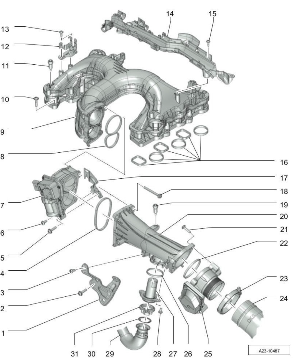
These are the published tightening values for the intake manifold procedure. Keep this page open while you reassemble. Anything marked “replace” gets a new part every time the joint is opened.
| Location | Type | Value |
|---|---|---|
| Intake manifold to cylinder head | 3-step sequence | 9 Nm6.5 ft-lb · see procedure |
| Holder for air guide pipe — fastening screws | Tightening | 9 Nm6.5 ft-lb |
| Intake manifold flap motor — fastening screws | Tightening | 9 Nm6.5 ft-lb |
| Location | Type | Value |
|---|---|---|
| Mounting pin on intake manifold for engine cover | Tightening | 5 Nm3.5 ft-lb |
| Holder for electric plug connections — screw | Tightening | 4 Nm3 ft-lb |
| Fastening screw for line guide | Tightening | 4 Nm3 ft-lb |
| Change-over valve holder for EGR cooler — screw | Tightening | 9 Nm6.5 ft-lb |
| Mounting pin on air guide pipe for engine cover | Tightening | 5 Nm3.5 ft-lb |
| Air guide pipe to throttle valve control unit — screw | Tightening | 9 Nm6.5 ft-lb |
| Location | Type | Value |
|---|---|---|
| EGR pipe to air guide pipe — fastening screw | Tightening | 9 Nm6.5 ft-lb |
⚠ See page 32 for the published 3-step tightening sequence.
Torque reference · sheet 2 of 3
EGR cooler.
EGR cooler assembly
| Location | Type | Value |
|---|---|---|
| EGR pipe to EGR cooler — use hot screw paste | Tightening | 9 Nm6.5 ft-lb |
| Screw securing EGR cooler | Tightening | 9 Nm6.5 ft-lb |
| Servo motor to EGR connection piece | Tightening | 9 Nm6.5 ft-lb |
| Location | Type | Value |
|---|---|---|
| Temperature sensor to EGR connection piece | Press-on force | 9 Nm6.5 ft-lb |
| EGR pipe to turbocharger — screw in by hand first | Torque + angle | 5 Nm + 90°3.5 ft-lb · then 90° |
| EGR pipe to connection piece — clamp, replace | Tightening | 5 Nm3.5 ft-lb |
| EGR connection piece to EGR cooler | Tightening | 9 Nm6.5 ft-lb |
| Coolant connection piece — securing screw | Tightening | 9 Nm6.5 ft-lb |
| Screw-type clamp — check position, replace | Tightening | 2.5 Nm2 ft-lb |
| Location | Type | Value |
|---|---|---|
| EGR cooler clamp at cooler — loosen / press back | Tightening | 5 Nm3.5 ft-lb |
Torque reference · sheet 3 of 3
Engine oil cooler & coolant flange.
Three screw positions, all to the same value. Four single-use seals — replace before reassembly.
Engine oil cooler & coolant flange
| Location | Type | Value |
|---|---|---|
| Mounting plate to engine block — screw | Tightening | 9 Nm6.5 ft-lb |
| Location | Type | Value |
|---|---|---|
| Engine oil cooler to mounting plate — screw | Tightening | 9 Nm6.5 ft-lb |
| Coolant shut-off valve to mounting plate — screw | Tightening | 9 Nm6.5 ft-lb |
⚠ Note · oil cooler seals
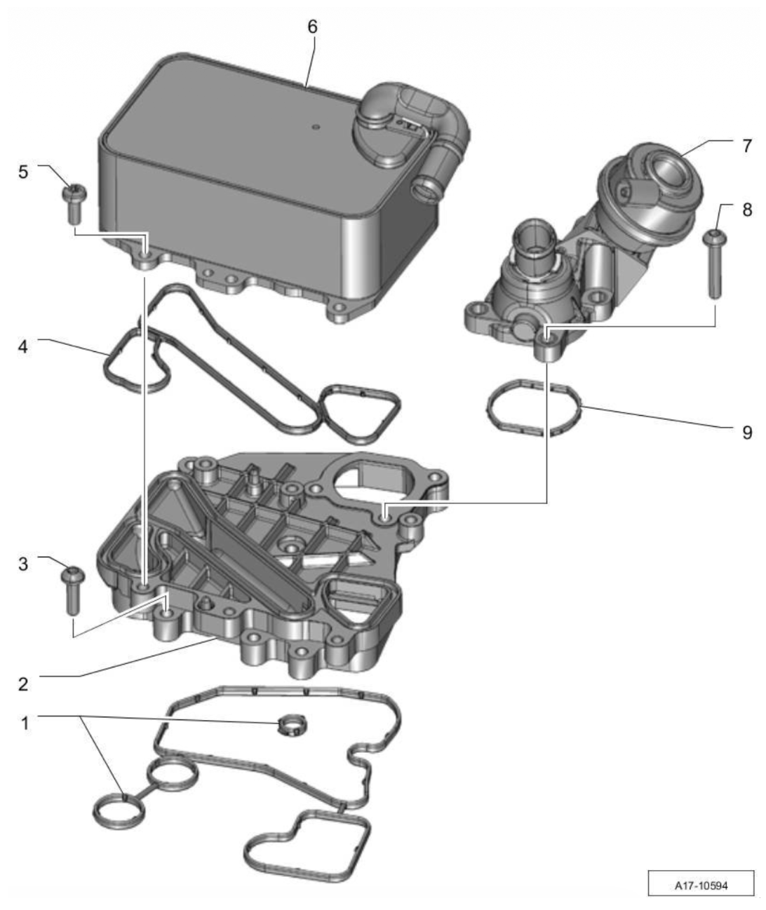
On the oil cooler / coolant flange assembly, the four seals (figure items 1, 4 and 9, plus the shut-off valve seal) are all replace-only parts.
 A23-10487
⚠ Caution · contamination
You are opening the high-pressure fuel side. Keep the work area clean, cap open fuel lines immediately, and follow standard diesel fuel-system cleanliness rules. A single contaminant in a high-pressure line can ruin the entire fuel system.
Preliminary work
- Remove the engine cover (design cover).
- Release the residual pressure in the cooling system: open the cap on the coolant reservoir briefly, then screw it back on until it engages.
Removal sequence · steps 01–06
Cable tray, high-pressure fuel line.
Unclip the harness and hoses from the cable tray using a plastic pry tool.
Move the harness and hoses towards the rear, out of the way.
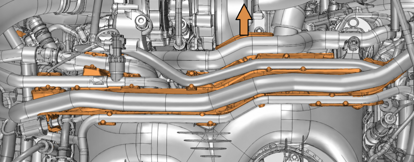
Unscrew the two cable tray fastening screws 2, 3 and lift the cable tray 1 off.
Unscrew the two holding-clamp screws and remove the holding clamp 1, 2, 3.
Unscrew the union nuts arrows and remove the top high-pressure fuel line.
Install dust caps immediately onto the exposed fuel rail male threads arrows to prevent dirt from ruining your fuel system.
Removal sequence · steps 07–13
Electric plugs, coolant valve, flap motor.
Take the two electric plug connections and the check valve out of their holder items 1, 2, 3.
Unscrew the fastening screw on the holding clamp for the high-pressure line 2, on the passenger side near the rear.
Disconnect the electric plug connection 2 on the coolant valve 1.
Unscrew the coolant-valve holder fastening screws (arrows) and move the holder with the valve aside.
Disconnect the electric plug connection (arrow) on the coolant temperature sensor.
Disconnect the two electric plug connections 1, 2 and move the wire harness to the left side.
Unscrew the fastening screw 3 on the intake manifold flap motor.
Removal sequence · steps 14–19
Dipstick, EGR clamp, air guide pipe.
Unscrew the fastening screw 2 that secures the guide tube for the oil dipstick 3.
Fully loosen and spread the screw-type clamp 2 on the EGR pipe.
Unscrew the fastening screws 2 on the holder for the air guide pipe.
Disconnect the electric plug connection 1 on the throttle valve control unit.
Loosen the screw-type clamp 3 and pull off the air guide hose.
Do not remove fasteners #2. Leave the throttle valve control unit mounted to the air pipe 2 — saves a gasket replacement.
Removal sequence · steps 20–24
Fuel pressure sensor, glow plugs, lift-off.
Using a 27 mm deep socket, remove the fuel pressure sensor (red circle). Optional, but much easier than fighting with it during manifold removal.
Disconnect the glow plug boots (red circles). Carefully pull upwards while twisting — they should pop out like a spark plug boot.
Unscrew the four intake manifold fastening screws in order 1 → 2 → 3 → 4.
Unscrew the remaining intake manifold fastening screws (arrows) in any order.
Lift the intake manifold off gently. Lift it up and slide it forward. It might seem impossible at first — you'll get it.
⚠ Note · keep ports clean
Immediately place shop towel balls into the exposed intake ports to keep dirt and dust out of the cylinders. Use your judgment on the ball size — snug, with zero risk of falling into the port.
⚠ Replace now
Replace the intake manifold seals on the cylinder head, the flap-motor seal, and the air-guide-pipe seals now. They do not go back in.
 A26-10980
⚠ Note · removed as a unit
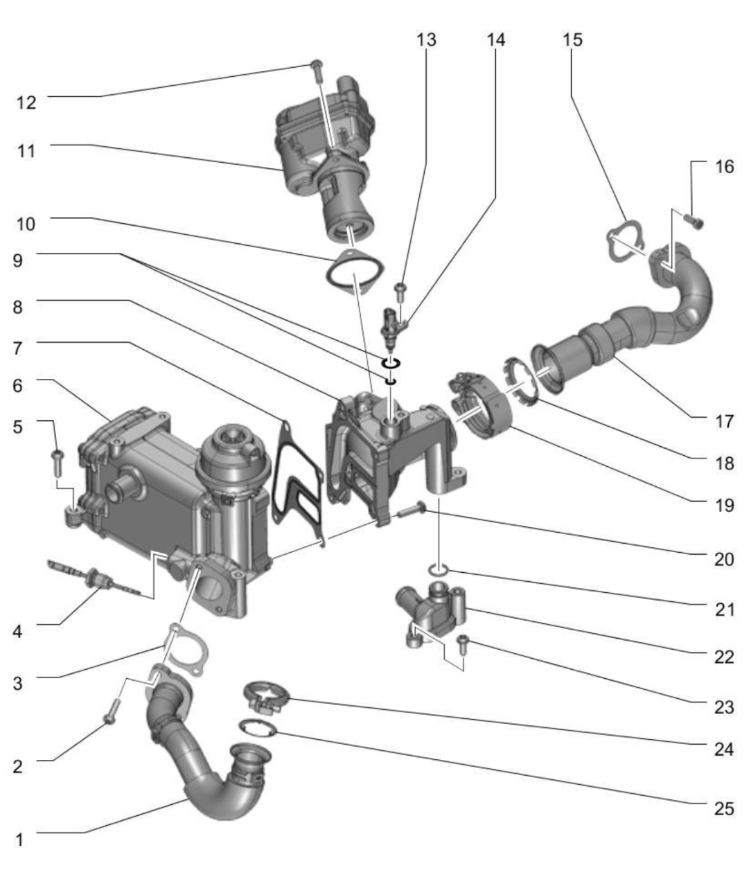
The EGR cooler comes out as a unit with the EGR valve. They are not separated on the engine.
Pull off the vacuum hose item 3.
Disconnect the electric plug connection item 1.
Loosen the screw-type clamp item 2 and press it back. On reassembly this clamp torques to 5 Nm (3.5 ft-lb).
Loosen the clamp item 4 and remove the coolant hose.
Unscrew the EGR cooler fastening screws (arrowed). On reassembly these torque to 9 Nm (6.5 ft-lb).
Pull the EGR cooler upwards as one unit. Be careful — the coolant intermediary flange is pressed into the EGR cooler from the underside. Pull gently upwards to separate both parts.
⚠ Reassembly note · EGR pipe-to-turbo screw uses torque + 90° (see page 30). EGR pipe-to-cooler screw needs hot screw paste.
 A17-10594
⚠ Note · shared mounting plate & prelim
The coolant shut-off valve (the coolant flange) sits on the same mounting plate as the oil cooler and is removed with it. Before starting: confirm the coolant is drained, the EGR cooler (Part 02) is out, and a cloth is placed around the oil cooler to catch escaping engine oil.
Loosen the clamp item 1 and detach the coolant hose.
Loosen the adapter on the shut-off valve and press it aside.
Unscrew the screws (arrowed) and remove the oil cooler together with the coolant shut-off valve flange.
Ref · drawing A17-10632Collect the residual fluid and dispose of it properly.
Build everything back up in the reverse order you took it apart: oil cooler and coolant flange first, then the EGR cooler, then the intake manifold last. Fit new seals everywhere a seal came out. Hose connections and air guide pipes must be clean and free of oil and grease. Spray the threads of any reused screw-type clamp with anti-rust agent before fitting.
⚠ Caution · sequence matters
Observe both the torque values and the tightening sequence. The intake manifold uses a specific 3-step pattern. Skipping the sequence can warp the flange and cause a leak.
4.1 · Oil cooler and coolant shut-off valve flange
- Fit new seals to the oil cooler, the mounting plate and the coolant shut-off valve items 1, 4, 9.
- Set the oil cooler and shut-off valve flange onto the mounting plate.
- Install all three screw types items 3, 5, 8: mounting plate to engine block, oil cooler to mounting plate, shut-off valve to mounting plate.9 Nm
- Reconnect the coolant hose and tighten its clamp.
- Reconnect the adapter on the shut-off valve.
Section 4.2 · sheet 1 of 2
EGR cooler assembly.
Fit new seals, gaskets, O-rings and replace-only clamps. The EGR pipe to turbocharger screw uses a torque-plus-angle spec. The EGR pipe to cooler screw needs hot screw paste.
- Fit new seals, gaskets, O-rings and the replace-only screw-type clamps.
- Apply hot screw paste to the EGR-pipe-to-cooler screw threads.
- Set the EGR cooler and valve unit onto the connection piece.
- Install the EGR cooler fastening screws.9 Nm
- Install the EGR connection piece to cooler screw.9 Nm
- Install the EGR pipe to cooler screw — hand-start first, with hot screw paste.9 Nm
Section 4.2 · sheet 2 of 2
EGR — turbocharger interface & final checks.
The torque-plus-angle step on the turbocharger interface is the highest-stakes fastener in this entire procedure. Hand-start it first — never spin it home with a power tool.
- Install the EGR pipe to turbocharger screw: hand-start, then 5 Nm, then a further 90°.5 Nm + 90°
- Fit the EGR-pipe-to-connection-piece clamp (new).5 Nm
- Install the coolant connection piece securing screw.9 Nm
- Fit the check-position clamp (new).2.5 Nm
- Install the servo motor screws and press the temperature sensor on.9 Nm
- Reconnect the coolant hose, the clamp at the cooler (5 Nm), the electric plug, and the vacuum hose.
⚠ Caution · PIWIS required if EGR valve replaced
If the EGR valve itself was replaced, the EGR drive-link test must be run with PIWIS Tester II (9818) under Maintenance/repairs. The PIWIS instructions take precedence over this manual if they differ.
Section 4.3 · sheet 1 of 2
Intake manifold — the 3-step torque.
Fit new seals, set the manifold, then follow the published 3-step torque sequence below. Do not freelance — the sequence is what keeps the flange flat.
⬢ The published 3-step sequence
Step 1. Run all screws in as far as they go by hand. Step 2. Torque to 9 Nm in the numbered sequence shown on the drawing. Step 3. Go around again at 9 Nm in any order.
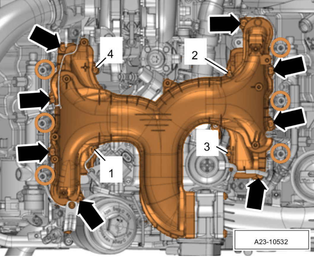 A23-10532
- Fit new intake manifold seals on the cylinder head, a new flap-motor seal, and new air-guide-pipe seals.
- Set the intake manifold in place and start all four manifold screws plus the arrowed screws.
- Tighten the manifold in three steps as published (see callout above).9 Nm × 3
- Reconnect the glow plug electric plug connections.
- Refit the coolant hose and tighten its hose clamp.
- Reconnect the throttle valve control unit plug and refit the air guide hose — air guide pipe to throttle valve screw.9 Nm
- Refit the left air guide pipe holder screws.9 Nm
- Tighten the EGR pipe screw-type clamp.
Section 4.3 · sheet 2 of 2
Intake manifold — harness, lines, cover.
- Refit the oil dipstick guide tube and its securing screw. Push the stoppers back in.
- Refit the flap-motor fastening screw.9 Nm
- Reconnect the two wire-harness plugs.
- Reconnect the coolant temperature sensor plug.
- Reposition the cylinder-head coolant valve holder, tighten its screws, reconnect its plug.
- Fit the high-pressure line holding clamp screw.
- Refit the electric plug connections and check valve into their holder.
- Refit the top high-pressure fuel line and tighten the union nuts. Refit the holding clamp (two screws).
- Refit the line routing and its two screws — line guide screw.4 Nm
- Reconnect the rear coolant hose and press the harness hoses back onto the line routing.
- Refit the engine-cover mounting pins: on the intake manifold (5 Nm), on the air guide pipe (5 Nm). Plug-connection holder screw (4 Nm).5 / 4 Nm
⚠ Note · pre-fit checks
Before you start the engine, double-check: every electric plug clicked home, every hose clamp seated and tight, no rags left in the intake ports, no tools on the engine, the dipstick guide tube is fully home, and the coolant cap is on the reservoir.
- Bleed the fuel system.
- Fill and bleed the cooling system (includes bleeding).
- Fill in engine oil and check the oil level.
- Install the engine cover (design cover).
- If the battery was disconnected, run the post-disconnect work instructions and battery trickle-charge as required.
- Start the engine, bring it to temperature, and check for coolant, oil, fuel and boost leaks at every joint you opened.
Section 06 · replace-only parts checklist
Short list of single-use items across all three procedures. Tick each before you button up.
- Intake manifold seals on cylinder headIntake
- Flap-motor seal on intake manifoldIntake
- Air guide pipe seals (flap motor and throttle body)Intake
- EGR pipe to connection piece clamps (two)EGR
- EGR pipe seal on air guide pipeEGR
- EGR cooler seals, gaskets and O-ringsEGR
- Oil cooler seals (figure items 1, 4, 9)Oil cooler
- Coolant shut-off valve sealOil cooler
Appendix · workshop notes
Your own observations.
Mileage, date, torque-wrench serial, parts numbers, things you'd do differently next time. Write it down — future-you will thank present-you.
End of document
Built once.
Built right.
If you found an error, a clearer way to phrase a step, or a torque value that doesn't match your wrench — let us know. We rev these manuals when the workshop tells us to.